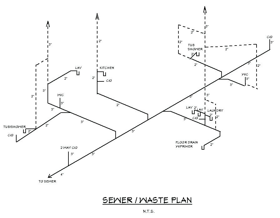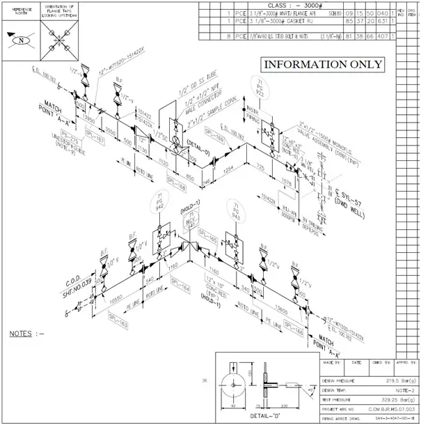
Straight lengths of all the pipe runs on the drawing are reported as clearly as possible.Isometric drawings carry a graphical representation of the 3 dimensional piping system being represented.Orifice meter taps orientation (it depends upon the pipe direction and fluid typeīOM section is a very important section, as it affects the cost of the project.Some may feel like they need online masters degree programs to understand this, but this post will bring you insight.Minimum gap requirement between the welds.Field weld and Workshop weld Identification.Structural penetration (if the line is crossing any structure).Control Valve location and arrangement.


The isometric drawing sheet consists of four major parts viz title block, drawing area, BOQ (Bill of Quantity ) section, and Special requirement notes section. To check the connection/end requirements for mounting the instruments. To check special items type and their dimensions To check elevation and orientation of connected nozzle To check line route, dimension, elevation, valve orientation and co-ordinates To check Design Pressure & Temperature, stress critical lines, Hydro test pressure, inspection class and type, etc. To cross-check line number, line size, insulation, special requirement notes (like no pocket, press head), etc. P&ID (Piping and Instrumentation Diagram) Documents Required for Checking Piping Isometric Drawing Documents


 0 kommentar(er)
